
Superior designs achieve arc flash safety in building electrical systems
Arc flash analysis is an important piece of designing electrical systems, especially in large amperage and utility service equipment applications
Learning Objectives
- Gain an understanding of what arc flash is, what can cause it and why it is dangerous if not considered properly in design.
- Review the code dictated safety requirements, such as working areas, key terms and personal protective equipment guidelines.
- Learn the basics of the code recognized arc energy reduction methods and how they are used.
Arc flash insights
- Designing a building’s electrical system to mitigate arc flash incidents is vital for electrical engineers to understand.
- NFPA 70E, along with other codes, standards and guidelines, guides electrical engineers and electricians in working with electrical equipment.
 This article has been peer-reviewed.
There are many concerns and challenges facing the construction industry, not least of which is electrical safety for facilities and the people maintaining those facilities. One of the most dangerous scenarios that can occur in a building is the possibility of electricity arcing from electrical equipment into a room where a person may be working. This poses a significant risk to nearby human life and to the building if a fire is started from the arc flash.
A reaction to this and a consideration for construction teams is the need for extended shutdowns of major electrical equipment providing power to these facilities during any future maintenance or renovation work. Rising concerns for human safety have caused more electrical contractors to refuse work on electrical equipment that is energized. Many electrical contracting companies even have put policies in place banning live work from being done by any person working for that company. Electrical designers must work around these challenges to provide safe and practical solutions mitigating any risks from arc flashes.
This article will look at the basics of arc flash, what can cause it and the potential hazards if it occurs. It will also cover general code requirements for safety and mitigation techniques. The primary codes referenced in this article will be NFPA 70E (2021): Standard for Electrical Safety in the Workplace and NFPA 70 (2023): National Electrical Code. All the details of arc flash are not able to be covered within this article, more information can be found in NFPA 70 and 70E.
Basics of arc flash
An arc flash occurs when electrical energy is released from a circuit or piece of electrical equipment into the immediate workspace around the equipment. This happens when there is an electrical short or fault current in the intended circuit that causes the energy to exit this circuit and travel to a different nearby circuit or path to ground, such as a person.
There are many reasons an arc flash may happen, including but not limited to an excess of dust or water on the circuit/equipment creating a conductive pathway for electricity, an accidental short caused by metal (such as a tool) connecting across circuits or terminals, degradation of older equipment creating damaged or exposed live parts or poor installation resulting in loose connections that create air gaps where electricity can arc.
Arc flash occurs in the forms of heat energy, both high-pressure and sonic blasts and electrical shock. Arc flashes can cause explosions with shrapnel flying from the electrical equipment in the immediate vicinity, as well as fires that can spread throughout the building.
A person maintaining the electrical equipment and potentially anybody else in the room with the equipment when an arc flash occurs risks very serious injury, including burns, soft tissue damage, hearing damage, lacerations or dismemberment and death. Any time work is going to be performed on or near live electrical equipment, precautions should be taken to be properly protected. Knowing how to be protected and what precautions to take is very important.
Arc flash safety requirements
NFPA 70E establishes the guidelines for electrical safety in the workplace. It defines many of the key terms and methods for arc flash in Article 130 (Work Involving Electrical Hazards). It defines three boundaries for working space and safety (130.5(E)).
The first is the arc flash boundary, beyond which serious or permanent injury due to arc flash should not occur. NFPA 70E sets the incident energy value for the arc flash boundary at 1.2 cal/cm2, which is the research-based incident energy that can cause a second-degree burn that will heal without permanent injury. Incident energy above this value can result in permanent damage or more serious injury.
The next boundary set by 70E is the limited approach boundary, which is the closest point any unqualified person, if escorted by a qualified person and in proper personal protective equipment (PPE), should approach a piece of electrical equipment with exposed live parts.
The closest boundary defined by the NFPA is the restricted approach boundary. This boundary is the closest point anybody should approach the equipment, including qualified personnel, unless they meet one of the two conditions established in 130.4(G), which states says anybody entering the restricted approach boundary must either be insulated from the energized live parts at greater than 50 volts with insulating gloves and sleeves or the energized live parts must be insulated from the person.
The limited and restricted approach boundaries are both shock hazard boundaries and are independent of the arc flash boundary. They are determined by the voltage of the equipment per Table 130.4(E)(a).
Proper PPE to enter an equipment’s arc flash boundary is determined by that equipment’s maximum incident energy. To gain an understanding of maximum incident energy, a risk assessment must be completed that calculates the energy levels for applicable electrical equipment. NFPA 70E allows two different methods for determining the arc flash boundary/maximum incident energy and required PPE.
The first method is detailed in Section 130.5; this method is to perform a full arc flash analysis on the entire electrical system to calculate the maximum incident energy and arc flash boundary for every piece of equipment in the system. The second method is detailed in Section 130.7 and uses tables and established values by the NFPA to calculate maximum incident energy and arc flash boundary based on the type, size and voltage of the equipment.
These two methods produce different calculated values and have slightly different PPE requirements. NFPA does not prefer either method; it is permitted to use either method for calculations on separate equipment items on the same electrical system. However, both methods may not be used on the same piece of equipment. For a single piece of equipment, only one of the methods can be used (see Table 1).

Table 1: Arc flash personal protective equipment (PPE) categories and incident energy ratings using both NFPA 70E methods. This table compares the similarities and differences between both methods. Courtesy: Certus Consulting Engineers
While the NFPA does not have a preference regarding which method to use, it is typically best practice to perform a system analysis per Section 130.5. This method will yield more accurate and specific arc flash values for the equipment and system, rather than table generated numbers that are more generic in nature.
To perform an arc flash analysis per 130.5, the entire distribution system is modeled in a power system analysis program, such as from SKM System Analysis Inc. or ETAP ArcSafety. The entire electrical distribution system must be modeled with the actual equipment that is purchased or installed. The software will then analyze, calculate and produce the results detailing the required information for all the applicable equipment.
The analysis yields exact values for the arc flash boundary and incident energy and provides a more precise understanding of the system. The design engineer must always design the arc energy mitigation techniques used for the electrical system, but it is common practice for the design engineer to delegate the short circuit, coordination studies and arc flash calculations to the electrical contractor during the construction phase. In this case, the engineer must carefully review the submittals for these items to ensure the components being purchased match the design intent and that the equipment meets code requirements for safety (see Table 2).

Table 2: An example of an arc flash analysis calculation table. The most important categories coming from this table are arc flash boundary and incident energy. Courtesy: Certus Consulting Engineers
In addition to NFPA 70E, NFPA 70 also has guidelines for arc flash safety. Article 110.16(B) of NFPA 70 requires all service equipment, other than in dwelling units, that is likely to require work or maintenance while energized at or above 1,000 amps, to have proper labeling that identifies the level of arc flash hazard. The label must be clearly visible on the equipment so that it is seen before performing any work on that equipment.
NFPA 70E 130.5(H) requires the arc flash label to contain the following information: system voltage, arc flash boundary distance and either the available incident energy/working distance or the arc flash PPE category (shown previously from NFPA 70E, Table 130.7(C)(15)(a)) or the minimum arc rating of clothing or site-specific level of PPE (see Figure 1).

Figure 1: An example of an arc flash hazard label. This label has the NFPA 70 130.5(H) required information on the label and meets all code requirements. Courtesy: Certus Consulting Engineers
Arc energy reduction methods
In addition to identifying the potential risks of arc flash, the codes offer requirements to help limit the potential risk. One of these is the requirement for arc energy reduction found in NFPA 70 Articles 240.67 and 240.87. These articles describe the requirement as well as provide methods that are approved per the code.
The goal of arc energy reduction is to reduce the amount of time it takes to clear the circuit and trip the circuit breaker or other overcurrent protective device (OCPD). Reducing the clearing time reduces the amount of arc flash energy because there are fewer electrical cycles for the arc flash to occur. If there are fewer cycles for the arc flash to release energy, then there will be less energy to cause damage to the equipment and surroundings.
Articles 240.67 and 240.87 require any overcurrent protection device over 1,200 amps (adjustable or static rating) to have arc energy reduction means. Note: An arc energy reduction method must be used for any OCPD where the maximum rating of the device is 1,200 amps or higher, even if the device is an adjustable circuit breaker and is set lower than that for its specific circuit. This section also requires documentation that explains the chosen mitigation method and proves that it reduces the clearing time below the available arcing current.
Article 240.67 lists five acceptable methods to reduce clearing time for fuses, while Article 240.87 does the same for circuit breakers with seven methods. While NFPA 70 covers arc energy mitigation requirements for both fuses and circuit breakers, circuit breakers are more common, so the methods focused on by this article will be those methods for circuit breakers.
There are seven methods for circuit breakers to reduce clearing time allowed in NFPA 70 Article 240.87, those methods are listed below:
-
Zone-selective interlocking (ZSI).
-
Differential relaying.
-
Energy-reducing maintenance switching with local status indicator.
-
Energy-reducing active arc flash mitigation system.
-
Instantaneous trip setting.
-
Instantaneous override.
-
An approved equivalent means.
ZSI uses circuit breakers in a protected piece of equipment to sense when a fault occurs and reduces clearing time of the fault by opening the breaker very quickly. When using a ZSI to reduce arc flash energy, the ZSIs must be installed on the molded circuit breaker (MCB) and all downstream breakers in that panel and then signal circuits must be installed between the MCB and all the downstream breakers.
If a fault is sensed in one of the downstream breakers it will send a restraint signal to the ZSI breaker and the downstream breaker will open immediately. The upstream ZSI breaker will only trip in a fault scenario when the fault occurs between the upstream and downstream breakers or if the downstream device does not clear the fault in adequate time. An additional benefit of this method, besides being automated, is that it will minimize the amount of equipment that is disrupted in a fault scenario because only breakers sensing a fault will clear the fault.
Differential relaying places a current-sensing differential relay at each point where current can enter or leave a protected piece of equipment or multiple pieces of equipment. This relay measures the amount of current entering the upstream side of the relay and measures the amount of current leaving the downstream side of the relay. If the sum of the currents entering and leaving the zone of protection isn’t zero, it signifies that a fault is occurring somewhere in the protected relay area and the relay will send a signal to the upstream breaker and open that breaker to clear the fault. Because differential relaying doesn’t affect selective coordination, it can operate without intentional delay and can clear a fault very quickly.
An energy-reducing active arc flash mitigation system uses sensors that are designed to detect the onset of an arc flash or fault by sensing the light emitted from a flash. When the sensors detect an arc occurring, they send a signal to open the upstream breaker immediately thereby limiting the incident energy.
Instantaneous circuit breaker trip settings use adjustable instantaneous trip settings in the circuit breaker that can be set based on the available fault current at that breaker. The instantaneous setting must be set to a lower level than the available arcing current calculated for the circuit breaker to meet the NFPA 70 Article 240.87 requirements. Note that when using this method, temporary adjustment of the setting is not permitted.
Instantaneous override describes a fixed setting in a circuit breaker that is intended to open the breaker very quickly in the event of a fault. Like instantaneous circuit breaker trip settings, the instantaneous trip setting for the override must be lower than the available arcing current for the circuit breaker. When the instantaneous trip is set below the available arcing current, most circuit breakers will open and clear the fault in fewer than three cycles (50 milliseconds). It should be noted that both instantaneous circuit breaker trip settings and instantaneous overrides are very low-cost options and simple to install.
ZSI, differential relaying, energy-reducing active arc flash mitigation systems, instantaneous trip settings and instantaneous overrides are all examples of systems that are designed into the electrical system and automatically open the overcurrent protection upstream of a fault so there is no manual intervention required. These systems are practical because they are designed to act immediately upon detection of an arc flash to clear the fault.
ZSI, differential relaying and energy-reducing active arc flash mitigation systems are more aggressive measures to reduce the clearing time of an arc flash and reduce arc energy. These three methods are more expensive than the two instantaneous methods of arc energy reduction.
Energy-reducing maintenance switches are manual devices that are designed to reduce arc energy by overriding a circuit breaker’s normally delayed tripping and switching it into a position to immediately open in the case of a fault. NFPA 70 Article 240.87 requires an indicating light that illuminates when maintenance mode is turned on and should be installed with the switch that it is indicating. The maintenance switch/indicator light is typically provided with the electrical equipment it is protecting.
The maintenance switch should only be switched on during maintenance of the equipment because selective coordination may not be achieved while in maintenance mode because the settings that provide protection to a person working on the equipment are not optimal for the normal operation of the system.
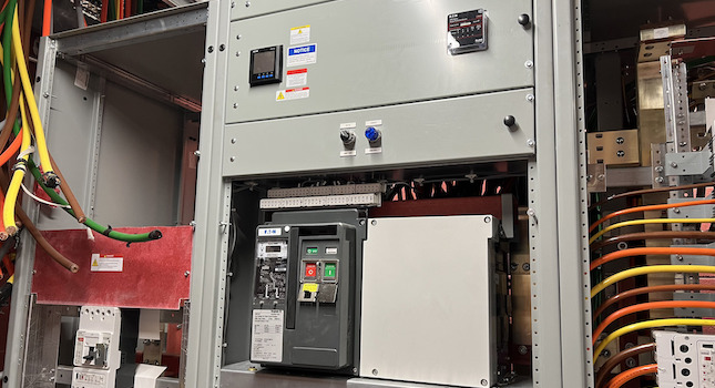
The primary weakness of an energy-reducing maintenance switch is that it requires a person to activate the arc energy mitigation protection and return it to normal operation. Either operation could be overlooked or forgotten by the staff working on the system, which is not a possibility with any of the automatic methods. This method of arc energy reduction is relatively cheap compared to some of the other methods listed (see Figure 2).

Figure 2: An example of an energy-reducing maintenance switch with a blue indicator light as part of the electrical equipment assembly. The blue light indicates when maintenance mode is activated for the equipment. Courtesy: Certus Consulting Engineers

Courtesy: Certus Consulting Engineers
How to select arc flash mitigation options
Arc energy mitigation is still relatively new to the electrical construction industry, so an approved equivalent means is provided in the code to be flexible to new, innovative methods to achieve arc energy mitigation and accomplish the intent of the code to provide a safer system.
There are several factors to consider when selecting which arc energy reduction method to design for an electrical system. When working in an existing facility, the existing electrical system may prevent the use of some of the methods that are not easily retrofitted into existing equipment and the cost and ease of retrofitting should also be considered.
In a new building, cost and preferences of the maintenance staff should be the primary consideration. An experienced staff may be comfortable working with an energy-reducing maintenance switch, while a less experienced staff may prefer a more automated approach, such as one of the other methods listed.
It is important to understand that complying with NFPA 70 mitigation requirements does not make it safe to work on energized equipment. The intent of the code is to make energized work less hazardous, not completely safe. Arc energy reduction is not helpful on large service equipment with incident energy above the NFPA 70E based 40 cal/cm2 where there is no safe PPE to work on energized equipment.
With an understanding of what arc flash is — as well as an understanding of the electrical dangers — it prevents and the code required mitigation techniques, designing the safest and most practical electrical systems possible for both maintenance engineering as well as building occupants can be accomplished.
Do you have experience and expertise with the topics mentioned in this content? You should consider contributing to our CFE Media editorial team and getting the recognition you and your company deserve. Click here to start this process.

Related Resources


