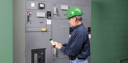
Case study: Hospital tower requires arc energy reduction
To keep occupants and workers safe in this hospital, electrical engineers used zone-selective interlocking (ZSI) breakers to mitigate arc flash incidents
The project design for a new hospital bed tower will include a new normal power utility service and a new generator system with associated normal and emergency branch panels to serve the building. The new building will use a 480/277-volt, 3-phase, 4-watt plus ground service from the utility. The goal of this example is to design the arc energy reduction system for the electrical equipment over 1,200 amps that is required by NFPA 70 (2023): National Electrical Code to have arc energy reduction.
It is determined a 2,000-amp normal power utility is needed and a 1,600-amp main switchboard is required to feed the emergency power system. From these main switchboards, the rest of the electrical system and downstream equipment is designed and sized to feed the building. The design determines that these two switchboards are the only two pieces of equipment over the 1,200-amp threshold.
The next step for this design is to perform an arc flash analysis to determine the incident energy, arc flash boundary and the necessary personal protective equipment (PPE) for the two pieces of main electrical equipment that require arc energy reduction.
For this example, SKM System Analysis Inc. software is used to perform the arc flash analysis calculations. Important inputs for this calculation are to obtain the available fault current from the utility company, the calculated fault based on the generator contribution, voltage and amperage ratings for all the major electrical gear, motor contributions and transformer impedances (see Table 3).

Table 3: Calculation results of the main switchboard and emergency switchboard arc flash analysis and associated arc flash hazard labels for the equipment. Courtesy: Certus Consulting Engineers
According to the results from the SKM calculation, both panels are above the 40 cal/cm2 threshold and they both have extreme arc flash boundaries exceeding 200 inches. This means that a person working in those electrical rooms is almost guaranteed to be working inside the arc flash boundaries.
Because both switchboards exceed the 40 cal/cm2 incident energy threshold, there is no safe PPE for working on either of these. With no safe PPE and a room encompassing arc flash boundary, neither of these switchboards should be maintained live under any circumstance. Doing so would result in certain permanent injury and/or death were an arc flash to occur while working in the room.
The example arc flash hazard labels from Table 3 need to be placed on each switchboard to ensure the level of danger is known to anybody entering the room and to ensure no work or maintenance is done to the equipment while operational.
Because these two switchboards fall above 1,200 amps, NFPA 70 Article 240.87 requires them to have arc energy reduction. Article 240.87 describes six different methods for achieving arc energy reduction; this is a new expansion so there are no existing methods for the building already established.
The method chosen for this design will be zone-selective interlocking (ZSI) breakers. This method has been chosen as it is a common, well-understood solution that works automatically. Automatically tripping in a fault condition is preferrable and it does not require a person to activate and deactivate the arc flash mitigation measures, which increases the safety in the system.
An additional benefit of this method is that it will aid in selective coordination by only opening the nearest breakers the fault, reducing the amount of the building that will experience downtime to a breaker trip.
This method is not without drawbacks. There is added cost to the circuit breakers installed in the two switchboards because the ZSI breakers are significantly more expensive than normal electronic trip circuit breakers typically used in switchboards for this type of facility. This method also adds signal circuits between upstream circuit breaker and the downstream breakers in the equipment enclosure increasing the labor and materials cost.
To accomplish the desired arc energy reduction using ZSI breakers, the ZSI breaker types must be used for the electrical equipment’s main circuit breaker, as well as all other breakers in the board feeding downstream equipment and loads. For this design, all circuit breakers in the two switchboards will be 100% rated, electronic trip circuit breakers with adjustable; long-time, short-time, instantaneous, ground settings; ZSI modules; and a signal circuit to communicate between the main circuit breaker and each downstream breaker in the switchboard.
The final design for ZSI is shown in Figure 3. It shows how this method can be used on contract documents and the symbology/terminology for ZSI breakers on one-line diagrams.

Figure 3: Final one-line diagram including zone-selective interlocking circuit breakers as the arc energy reduction method. Courtesy: Certus Consulting Engineers
Following the code requirements set by NFPA 70 and NFPA 70E (2021): Standard for Electrical Safety in the Workplace — and using the proper considerations when evaluating electrical systems for arc flash safety — will ensure a safer, more maintainable building for anybody working in these spaces in the future.
Do you have experience and expertise with the topics mentioned in this content? You should consider contributing to our CFE Media editorial team and getting the recognition you and your company deserve. Click here to start this process.


