
How to prevent shock and arc flash hazards in electrical systems
This article serves as a guide to understanding electrical hazards and establishing electrically safe work environments
Learning Objectives
- Identify what electrical hazards to look out for.
- Understand the basics of existing codes and guidelines for safety-related work practices.
- Recognize ways to reduce risk while working on or near electrical equipment.
Hazard insights
- Shock and arc flash hazards can cause serious injury or death. Adhering to the best electrical safety practices can help protect employees.
- Understanding what an electrical hazard is and how to mitigate it is key for any personnel working with electrical equipment or in an electrically related field.
 Both employers and employees have responsibilities when it comes to safety, particularly electrical safety. It is the employer’s responsibility to provide a workplace that is free of hazards that could result in death or serious harm per Occupational Safety and Health Administration’s (OSHA) General Duty Clause. It is the employee’s responsibility to follow and implement the safety protocols provided by the employers.
NFPA 70E: Standard for Electrical Safety in the Workplace creates standards for electrical safety. While the first chapter outlines safety-related work practices, it does not equate to official training.
Electrical safety standards, guides and codes
Standards, industry guides and codes relating to electrical safety include, but are not limited to the following:
-
OSHA 29 CFR 1910, Subpart S: Addresses electrical safety requirements and mandates that any employee who might encounter an electrical hazard must receive electrical safety training.
-
IEEE 1584, 2018: Provides guidelines for performing arc-flash hazard calculations.
-
NFPA 70: National Electrical Code (NEC) 2023: Guidelines for the installation of the electrical equipment.
-
NFPA 70E: Standard for Electrical Safety in the Workplace, 2021.
It is crucial to understand who is and is not considered a qualified person to promote electrical safety. A qualified person has skills and knowledge related to the construction and operation of the equipment and installations and has received safety training to identify the hazards and reduce the associated risk. They can perform tasks such as testing, troubleshooting and voltage measuring where an electrical hazard can exist.
Per NFPA 70E, Article 110.6 (A)(3), a person can become unqualified if they are not trained every three years. Additionally, a qualified person is not necessarily qualified to work on all equipment. They may be considered qualified with respect only to the specific equipment and tasks for which they have been trained.
While an unqualified person cannot work on equipment that has potential electrical hazards, they still require training. Per NFPA 70E 110.6 (A)(2), any unqualified person needs to be trained and familiar with any electrical safety-related procedures or practices that are necessary in their work.
Electrical hazards come in many forms including stripped insulation, improperly installed equipment and damage that modified the original equipment installation. These hazards may result in a shock, arc flash or blast event.
Shock hazards
A shock hazard is the presence of a potential shock to a person, caused by touching or being near exposed energized electrical conductors or circuits. Shocks occur when parts of a person’s body complete a circuit between an electrical source and ground, with current flowing between the two points through the person’s body. It is not necessary that a person touch the electrical source for a shock to occur as a high enough voltage gradient can create an arc through air or another otherwise insulating material.
The greater the voltage difference between the source and ground, the greater distance a person must be to remain safe. The distance a qualified person is allowed near a source where shock hazard is present is known as the restricted approach boundary, whereas the distance for an unqualified person is known as the limited approach boundary.
Figure 1 illustrates the two approach boundaries for shock hazards.

Figure 1: An example of an approach boundary, showing an open and energized panelboard where energized parts are exposed. Courtesy: CDM Smith
High-voltage shocks are a serious and deadly matter and it does not take much to cause serious or fatal damage. Even shocks from 120-volt (V) circuits can cause serious injury or death.
It is important to understand the relationship between current, voltage and resistance. Voltage represents an electric potential or difference in charge of two points, resistance is the opposition to the flow of current and current is the flow of charged particles, such as electrons or ions, through a material.
This relationship is represented by the following equation, commonly known as Ohm’s Law:
V = IR
V = Voltage, in units of volts
I = Current, in units of amperes (A)
R = Resistance, in units of ohms
This equation means that any increase in current or resistance will increase voltage. If there is an established voltage differential in a location, any increase in resistance will also reduce current.
It is important to take the body’s resistance into consideration. The internal body has a resistance of about 300 ohms, while the skin has resistances 1,000-100,000 ohms. This variance depends on which areas of the body make contact, the amount of moisture on the skin, condition of the skin and other factors.
For instance, if someone accidentally completed a 120-volt circuit with their hand and their body resistance at those points totaled to 50,000 ohms, the shock delivered would result in 2.4 milliamperes (mA) of current through the body. While this may cause pain, it wouldn’t be a deadly incident. However, if their body resistance at those points was 1,500 ohms, the resulting current would be 80 mA, enough to cause ventricular fibrillation if the current passed through their heart.
Meanwhile, a common circuit breaker or fuse in a house will only open or trip at 15/20 A. This is unless the circuit breaker is a ground-fault circuit interrupter, which can trip at 6 mA, based on the difference of the current in the circuits primary path. See Table 1 for a list of effects various amperages can have on the human body.
Understanding how little current it takes to cause harm, drives home the importance that resistance has in electrical safety during design and while working in the field. A person wearing personal protective equipment (PPE), such as electrically rated safety boots or gloves, may increase their resistance and therefore, reduce the risk of a shock hazard.
However, there is a limit to how much protective gear and a good ground system can help mitigate shock hazards. It is important to practice good safety practices, to keep distance, only work on or near live parts if necessary. If safe working conditions are not possible, shut off equipment before working on it using a lock out tag out procedure. Table 2 shows NFPA 70E recommended distances from various voltage sources.
In certain situations, energized conductors, such as bare overhead lines or platforms, can move due to wind or other outside forces, meaning the distance cannot be controlled by the employee. Due to the lack of control in the distance from the energized and open equipment, the approach distance for an unqualified person will increase. The restricted approach boundary will remain unchanged, however. Whether the energized equipment is moving or not, the qualified person should be equipped with the skills and knowledge to handle different situations. A good rule of thumb is to not stand in front of the energized equipment when it is being opened. If any electrical hazard should happen, it’ll propagate toward the open space.
Arc flash hazards
An arc flash hazard exists when personnel working on or near electrical equipment is exposed to arc flash incidents. An arc flash is the release of energy caused by an electrical arc, producing bright light, high temperatures and a shock wave, at very high arcing currents. An arc flash can be created for several reasons. One major cause is voltage spikes from lightning strikes or switching loads, which create a large amount of energy over a few microseconds. Other causes can be due to gaps in insulation, worn or loose connections, improperly installed parts or a buildup of dust or corrosion.
An arc flash can blind someone, create deafening sound waves, throw a person across a room, cause third degree burns and result in death. The potential severity of an arc flash incident depends on several factors: the possible size of the arc flash incident, the distance from the arc flash and the PPE worn. The contributors to the potential size of an arc flash incident are the available fault current, equipment shape, electrode configuration and the clearing time.
The available fault current is the amount of current that can be supplied during a fault incident. The fault current available at a given piece of equipment is based on distance from the supply current, resistances in wires and other equipment which will lower the available fault current and step-down transformers which will increase the current. This is why the available fault current must be calculated at each point in the system.
The clearing time is the amount of time it takes for an overcurrent protective device, such as a circuit breaker or fuse, to open during a fault incident. For the same fault current, the longer it takes for the overcurrent protective device to open, the larger the arc flash incident will be. For instance, a high available fault current incident could end up creating a small arc flash incident if opened quickly, while a small available fault current could create a large arc flash incident if opened slowly.
To inform personnel working near or on equipment susceptible to arc flash hazards, it is important for the facility to have an up-to-date arc flash study with arc flash hazard labels placed on the equipment. These labels provide information regarding the potential energy of an arc flash hazard, the appropriate distances to approach the equipment and appropriate PPE that should be worn around the equipment.
To ensure this information is accurate, it is required per NFPA 70E that the arc flash study be updated and reviewed at least every five years and after major modifications or renovations to the electrical system. If identified as necessary, the arc flash labels should be updated and replaced based on the new study.
Like shock hazards, the closer you get to equipment, the greater the risk involved. For arc flash hazards these distances are broken into a working distance, often 18 or 36 inches from the equipment, and an arc flash protection boundary. The working distance is the distance for electrical workers and other trained professionals wearing the appropriate level of PPE. The arc flash protection boundary is the minimum distance required for unprotected personnel to receive no more than second degree burns from a potential arc flash incident, which is equivalent to an incidental energy of 1.2 calories per centimeters squared (cal/cm2). The arc flash boundary is not solely dependent on voltage but is instead calculated as part of the arc flash hazard assessment.
When working within the arc flash protection boundary it is important to wear proper PPE. The PPE equipment is rated based on the potential incident energy, in cal/cm2. This can start with wearing a face shield, a long sleeve shirt, gloves, pants and safety boots at 40 cal/cm2. At 40 cal/cm2 or higher a full body arc flash suit is required.
At exceptionally large arcing currents, a powerful enough arc blast may be created that eliminates many of the protections electrical PPE provides. The blasts can become so powerful that the equipment will explode into shrapnel and propel anything or anyone in its path across the room. Because there are no calculations for determining the blast hazards that may be present, it is especially important to follow the proper rules and guidelines to ensure safety around electrical equipment.
Electrically safe work conditions
An electrically safe work condition (ESWC) is a state in which a circuit or equipment has been disconnected completely from energized parts, locked and tagged in accordance with established standards per NFPA 70E 120, tested to verify the lack of energized parts and, if necessary, temporarily grounded for personnel protection.
Any equipment operating at or above 50 V is required per NFPA 70E 110.3 to be completely de-energized if the employee is required to be within the limited approach boundary or the employee needs to interact with the equipment and there is a remote possibility that an injury could result from an exposure to an arc flash hazard — regardless of whether the energized parts are exposed or not.
There are only four allowances for when work on energized equipment is allowed per NFPA 70E, Article 110.4:
-
There are additional hazards or increased risk when de-energizing (i.e., exposure to other potential hazards such as chemical, mechanical or environmental when de-energizing equipment).
-
It is infeasible to de-energize an equipment due to the equipment design or operation limitations (i.e., performing diagnostics and testing of electrical circuits that can only be performed with the circuit energized).
-
The energized circuits do not present an electrical shock hazard. This typically includes equipment less than 50 V. The possibility of risk of exposure to electrical burns or explosions must be considered. If there is potential for an arc flash, work on equipment is not allowed unless it satisfies the first two allowances.
-
Normal operation of the equipment is allowed when it is in a normal operating condition (i.e., equipment door is closed, or equipment cover is placed and secured as manufacturer’s intended purposes). This is assuming that the equipment is properly installed, maintained and used in accordance with manufacturer’s instructions, listing and labeling. In addition, there must be no evidence of arcing, overheating, loose/bound equipment parts, visible damage or deterioration. This allowance is more for the interaction with and not work on the equipment. For example, installing plug-in circuit breakers is not considered normal operation.
When energized work is permitted to be performed, an energized electrical work permit is required per NFPA 70E 130.2(B). The energized electrical work permit must document the description of the equipment worked on, the location of the equipment, the work to be performed, the justification for why the work needs to be performed while the equipment is energized, how safety will be implemented, results from a power system analysis study, the means to restrict access of unqualified persons in the work area, evidence of job briefing and an energized work approval signature from the responsible management or owner. The power system analysis study results must show the voltage, approach boundaries, incidental energy, PPE requirement and the equipment required to safely perform the assigned task.
The hierarchy electrical hazard risk control methods
The most important question that should be considered before any risk control method is, “Do people feel safe, comfortable and confident working on the electrical equipment?” The risk control methods mentioned previously serve to boost the confidence an employee feels for their safety while working on the electrical equipment.
Per NFPA 70E, Article 110.5(H)(3), risk assessment procedures require implementation of preventive and protective risk control methods in the following hierarchy. The risk control methods are ordered from the most effective method to the least effective method. Although every risk assessment isn’t detailed in the following, being able to identify, analyze and evaluate the risk is important to determine the best risk control method(s).
Elimination: How can potential accidents be stopped? This risk control method removes the electrical hazards at the source and effectively accounts for human errors, such as accidentally brushing against an energized conductor. The best way to remove the electrical hazard is to completely de-energize the equipment and establish an ESWC.
In the case that the equipment cannot be de-energized, other control methods, such as the administration or engineering controls, should also be considered. For example, if work needed to be done to an existing switchgear that provides power to multiple buildings that need 24/7 operation. The building occupants should first be notified of the shut down in advance of the work timeframe and solutions, such as bypassing the switchgear before de-energizing it completely, can be considered to effectively eliminate electrical hazards.
Substitution: What other equipment should be considered for a safe system? Safety should be considered during the design stages and not after everything is built and done. Substitution is a risk control method that considers alternative design options that could limit the number of electrical hazards. For example, the amount of incident energy can be reduced by replacing 120 V control circuits with 24 V control circuit or by installing circuit breakers with a maintenance mode setting switch. Circuit breakers with maintenance mode are designed to temporarily reduce the short-time delay setting of the circuit breaker, typically using a separate analog trip circuit that provides faster interruption times and significantly lowers incident energy level.
This doesn’t necessarily help the employee avoid shock hazards, but by performing a power system study to better understand the electrical system and the amount of energy produced from each equipment in the system, it can help the employer and employee better understand what protective equipment is better for reducing the energy level.
Engineering controls: How can the employee be separated from the hazard? Engineering controls remove hazardous conditions by placing a barrier between the worker and the hazard. For example, a guard using shutters or plastic covers for live or energized parts doesn’t have high chance of arc flash blast (see Figure 2).

Figure 2: This figure shows a power terminal cabinet with a plastic cover guarding the live/energized parts. Courtesy: CDM Smith
Other considerations that could be done, especially during the design stage, are systems with dual feeds, tie circuits or bypass switches that allows planned shutdowns for maintenance. By having a bypass, the employee can effectively isolate and de-energize the equipment of concern.
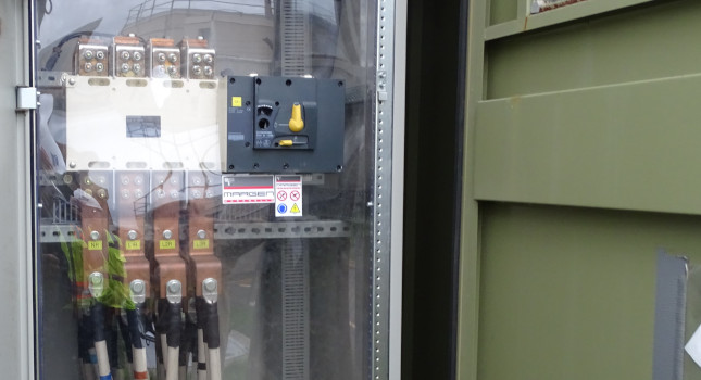
Awareness: Is there enough information to identify the risk? Identification of the equipment and hazard present will allow the employee to easily identify the potential risk. In addition to an arc flash label that details the boundaries, incident energy and PPE, equipment should also have labels identifying voltage, where it’s fed from and what it feeds (see Figure 3).

Figure 3: An arc flash label details boundaries and personal protective equipment requirements. Courtesy: CDM Smith
Administration controls: How can safety be best communicated? Administration controls improve safety through policies, practices and procedures. Accurate documentation is key for this kind of risk control. Documentation can include verification of proper maintenance and installation, details of the lockout/tagout programs, written electrical safety procedures and training requirements. Communication between employer and employee is important for this risk control method as it can better modify policies, practices and procedures that are suitable for the people working in the facility.
PPE: What should be worn? PPE be considered as a solution only after all other risk control methods have been exhausted. Even then, it should not be the only control element, as it is the least effective and provides the lowest level of safety control.
PPE should be rated for the incidental energy of the equipment as determined from an arc flash study. All conductive material, such as jewelry or belts should be removed when working on an electrical part. Leather work shoes or dielectric overshoes are required when insulated footwear is used. Because one of the biggest worries in shock hazard is completing the circuit, insulated footwear can prevent shock that comes from stepping on energized conductors or parts.
Do you have experience and expertise with the topics mentioned in this content? You should consider contributing to our CFE Media editorial team and getting the recognition you and your company deserve. Click here to start this process.
Related Resources


