
Specifying low-voltage variable frequency drives
Understanding different types of low-voltage VFDs and how to specify them is an important ability for electrical engineers
Learning Objectives
- Learn the purpose and advantages of variable frequency drives.
- Understanding major design considerations when choosing to use variable frequency drives.
- Knowledge of common types of variable frequency drives.
 Variable frequency drive insights
- With proper consideration, a VFD can provide an efficient method for controlling a motor’s speed, lower electricity costs and reduce the inrush currents that accompany a motor as it is first energized.
- This article focuses on advantages and major design considerations when specifying a VFD, accounting for cost, efficiency and harmonic distortion. Information about the common types of VFDs is also included.

Figure 1: A 25-horsepower 6-pulse variable frequency drive installed at a wastewater treatment plant. Courtesy: CDM Smith
When it comes to starting and running industrial motors, such as blowers or compressors, there are several options available, including but not limited to, across-the-line starting with a motor circuit protector, reduced voltage auto-transformers, reduced voltage soft starters and variable frequency drives. The across-the-line option is the cheapest but is not recommended for larger motors as in-rush currents will be largest with this starting method, often six to eight times the motor’s normal operating current. This can create a need for oversized electrical equipment, which will typically cost more than the savings from the starter.
An RVAT, RVSS and VFD can all be used to reduce the in-rush currents created by a motor during startup. While the RVAT and RVSS are similar in cost, the VFD can be five to 10 times more expensive than these other two options depending on the type of VFD chosen.
However, the increased cost comes with some additional benefits and capabilities:
- Improved power factor — achieved with the use of direct current bus capacitors within the VFD. This is because the dc bus capacitors provide the needed reactive current to the motor, required to induce the rotor’s magnetic field and the input supply line only has to be real power with the voltage and current almost perfectly in phase. The benefits of improving power factor include avoiding power factor penalties from the utility, reducing demand charges from the utility and reducing the current carried by the distribution network.
- Extended motor life — caused by controlling motor current, moderating start and stop functions and reducing the wear and tear on the motor. This can lead to reduced replacement costs by reducing how often a motor needs to be started and stopped and providing a smoother transition. However, long VFD motor feeder lengths can cause reflected waves and the slower shaft speed of the VFD can cause cooling issues for totally enclosed fan-cooled enclosures. These are potential issues which need to be addressed.
- Speed control — an ability for a VFD to produce a varied frequency, which can be used to control the speed of a motor based on its needed output. This can be done using open loop or closed loop control. For open loop control method, the volts/Hertz output to the motor is controlled independent of feedback from the motor. This can be done using linear or custom nonlinear output curves. To ensure the VFD is providing accurate speed control, there is a tuning mode, which can be used to compensate as needed. For the closed loop control method, the VFD will monitor the voltage and current of the motor via the power leads and determine the motor speed. This allows the VFD to vary the output voltage and current to achieve the required torque and desired speed. Each control method is useful for different types of motors and provide a useful tool for applications that require precise or varied motor speeds.
- Reduced energy consumption — lowered by reducing load demands for motors, which do not need to run at 100%. This benefit is often the most important and provides more cost savings than may be first thought. This is because of how affinity laws work for centrifugal pumps. These affinity laws express mathematical relationships between variables involved in pump performance and are useful for predicting the effect of speed on pump performance. Based on the affinity laws, a 50% reduction in rotational speed will reduce the power used to 12.5%. Even a pump rotational speed of 90% will reduce the power required to 73% and a pump rotational speed of 75% will reduce the power required to 42%. This means small reductions in speed can provide major energy savings potential.
Often, these advantages are enough to outweigh the additional upfront cost of the unit, especially when speed control is a necessity.
When choosing a VFD, there are some additional considerations, which must be made that could otherwise be cause for concern. The following are some of the major items to consider:
- Harmonics — deviation of the ac power sinusoidal wave form caused by a nonlinear load, resulting in the flow of harmonic currents in the ac power system. This harmonic distortion has effects on both linear and nonlinear loads, as well as propagating through the utility source and affecting other users. The harmonics can cause capacitor banks to fail, trip circuit breakers, burn out motor windings and cause transformer overheating. For these reasons, it is important to consider mitigations to curtail harmonic distortion. This can involve choosing the appropriate VFD to specify or installing external harmonic correction units. It is recommended for the design engineer or other involved parties to perform a harmonic study to ensure harmonics are being properly mitigated. An important reference for harmonic control is the IEEE-519 Recommended Practices and Requirements for Harmonic Control in Electric Power Systems standard, which focuses on preventing one utility customer from causing harmonic problems for another utility customer or the utility itself.
- Reflected waves — over-voltages caused by the quick switching of insulated gate bipolar transistors used in modern VFDs. When not mitigated, these reflected waves put stress on cable insulation, motor insulation and the motor windings. This ultimately causes damage and reduces the life of the equipment. This damage happens because the reflected waves create peak voltages higher than what the motor and motor leads are rated for. Some options for mitigating reflected waves include the following:
- Specifying inverter duty motors, which are capable of withstanding higher peak voltages. Inverter duty motors withstand higher peak voltages by using voltage spike-resistant insulation systems, which may include inverter-grade magnet wire, improved insulation and low heat rise designs. These improvements allow an inverter duty motor to withstand an upper limit of 3.1 times the motor’s rated line-to-line voltage, per National Electrical Manufacturers Association MG 1 Part 31. For a motor rated at 460 V, this comes out to a peak voltage of 1,426 V.
- Specifying the VFD to be equipped with a load reactor to provide a buffer between the motor and VFD. The load reactor can reduce the effect of reflected waves and increase load inductance. The load reactor is recommended for noninverter duty motors greater than 100 feet away from the VFD or inverter duty motors greater than 300 feet away from the VFD. The load reactor should be placed as close to the VFD output as possible to be effective and will typically protect the motor about 500 feet away from the VFD.
- Installing dv/dt output filters to limit the peak voltage. Dv/dt filters work by changing the voltage rise time and slowing pulse width modulation pulse transitions. These filters provide longer range motor protection compared to load reactors, up to about 2,000 feet away. It is recommended to install a dv/dt output filter when the VFD and motor are over 500 feet from each other.
- Installing a sinewave filter to convert the rectangular PWM output signal into a smooth sine wave voltage, thereby removing the voltage spikes. Because this filter works by creating a sinewave, there is not limiting distance. Due to the increased cost, it is not recommended to use this filter unless the VFD is located about 2,000 feet away or more
- Limiting the distance between the VFD and motor. By limiting the distance between the VFD and motor, costs can be saved by not having to purchase ever increasingly more expensive filters, not to mention the costs saved from the length of cables as well as the increased size of cables required due to voltage drop.
- Electromagnetic interference — electrical signals, also known as “noise,” caused by multiple drives located in an area. These electrical signals can appear in control systems and produce undesirable effects in the system, such as communication errors, reduced equipment performance and malfunctioning or nonoperating equipment. Mitigation measures include installing EMI filters, ensuring a low impedance ground system, installing VFD shielded cable or installing a common mode choke.
- Heat loss — considerable amounts of heat are generated from multiple parts of the VFD process during power conversion from alternating current to dc and dc to ac. The VFD switching frequency can be lowered to reduce heat generation in the drive but lowering the frequency will increase the creation of harmonics and the audible noise heard from the motor. The primary method for preventing overheating of the equipment is using heat sinks and fans to dissipate the heat through vents in the enclosure. If possible, it is ideal to place VFDs inside a climate controlled electrical building or room. However, there are multiple vendors that can provide external VFDs with an air conditioning unit. The HVAC system will need to account for the added heat generation as VFDs can quickly raise the indoor ambient temperature. It is best to reach out to VFD manufacturers to determine the expected heat generation.
Common types of variable frequency drives
A VFD is used to control the speed of inverter duty ac motors. It consists of a rectifier, dc bus and inverter. The rectifier converts the ac power to dc power. The dc bus smooths out the dc power by using an inductor capacitor filter and the inverter converts the dc bus to a simulated, pulse-width modulated, sine wave using IGBTs, which switch on and off. While the inverter and dc bus portions of a VFD remain the same, the rectifier portion depends on whether a multi pulse or active front end drive is selected.
6-, 12- and 18-pulse drives

Figure 2: A standard 6-pulse circuit diagram. Courtesy: CDM Smith
The cheapest and simplest VFD is a 6-pulse VFD, which uses a three-phase full-wave diode bridge, consisting of six rectifier devices, from which it gets its name (see Figure 2). The downside to this configuration is that the current draw at each diode bridge is not uniform and when the supply is not perfectly balanced the drive will produce harmonics. While this may not be a problem for smaller motors, it can be a concern for larger motors, especially when the amount of total load on the VFD increases.
To reduce harmonics, a 6-pulse drive can be upgraded to a 12- or 18-pulse drive. This is done by using 12 rectifier devices or 18 rectifier devices, effectively paralleling the 6-pulse drive rectifiers two or three times, respectively.
However, these configurations require an added transformer connected to the beginning of the circuit. This transformer consists of a primary side winding with two secondary windings each phase shifted 30 degrees apart for a 12-pulse drive and with three secondary windings each phase shifted 20 degrees apart for an 18-pulse drive. These transformers are necessary to create phase shifts, which help to displace the harmonics currents, so they cancel each other out.
The 30-degree phase shift from the 12-pulse drive cancels out the 5th and 7th harmonic currents, while the 20 degree phase shift from the 18-pulse drive additionally cancels out the 11th and 13th harmonic currents.
Many manufacturers have created new techniques using autotransformers to achieve the required phase displacements. However, the addition of this extra component along with the extra rectifiers and convertors adds extra cost, increases the size of the units and generates more heat.
Due to these disadvantages, it is often more beneficial to only use 6-pulse drives for smaller motors, 100 horsepower or less and switch to either 18-pulse drives or alternatively the more modern AFE drives for larger motors. It is not recommended to ever use 12-pulse drives as they cost approximately the same as an 18-pulse drive, has less benefits than an 18-pulse drive and many manufacturers no longer make them. Many manufacturers make 24-, 36- and 54-pulse drives, but these are for much larger motors, up to 10,000 horsepower, that are often medium voltage.
Active front end drives

Figure 3: A standard active front end (AFE) circuit diagram. Courtesy: CDM Smith
AFE drives are an alternative to multipulse drives, especially for 12- and 18-pulse drives, which are more expensive, less efficient, take up more space and are worse at mitigating harmonics. Instead of having a passive rectifier section consisting of multiple diodes and a transformer, the AFE drive uses an active rectifier section using IGBTs, similar to the inverter section of multipulse drives (see Figure 3).
The advantage this provides is that the IGBTs switching on and off can draw a nearly perfectly balanced power supply for the drive by filtering out harmonics generated by the VFD at any given moment. This is done by creating harmonics that cancel out and effectively eliminate the harmonics that would be created by a standard 6-pulse drive. The end result is an efficient ac output with minimal harmonic distortion.
An additional advantage of AFE VFDs is the ability to regenerate energy back to the utility source or other system loads. This regeneration happens during the motor braking process, which is the period of time when the motor has been shut off. Normally, when a motor is suddenly shut off the excess energy becomes unwanted heat, requiring braking resistors and cooling equipment to dissipate this heat and prevent damage to the motor.

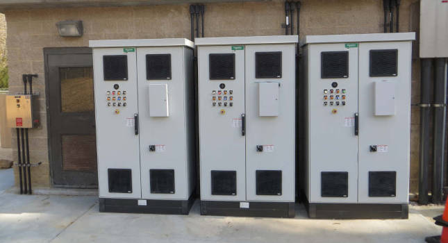
Figure 4: This shows three 150 horsepower variable frequency drives VFDs within NEMA 3R enclosures. Courtesy: CDM Smith
When a drive has built-in regenerative capabilities, the motor can be rapidly stopped and reuse the excess power without the need for extra heat dissipation. The excess power will be sent back to the utility grid or used to power other facility equipment. This can be especially useful for applications that require high-inertia loads, such as cranes and hoists that require frequent braking.
If the motor load makes up a large portion of the facility demand and the facility is disconnected from the utility, the motor generating power could create a voltage spike, tripping circuit breakers. To mitigation this issue a battery or capacity bank could be installed to absorb the excess power generated.

Figure 5: Technicians work inside one of the 150 horsepower variable frequency drive enclosures. Courtesy: CDM Smith
Joshua Hunter, PE, is an electrical engineer at CDM Smith, focusing on the design and analysis of electrical power systems.
Do you have experience and expertise with the topics mentioned in this content? You should consider contributing to our CFE Media editorial team and getting the recognition you and your company deserve. Click here to start this process.

