
Transformer, switchgear and UPS design considerations
Several key and common engineering decisions to consider when designing a power distribution system are highlighted in a case study example.
Power generation insights
- A power distribution system has many different aspects that need to be considered because a fault or mistake can lead to major issues regardless of the type of facility.
- The case study highlights several challenges the electrical engineering team faced and how they had to work through these problems by revisiting or revising what they had done to ensure the project would be successful.
Transformers, switchgears and uninterruptible power supplies (UPS) equipment are crucial parts of the electrical power system. Transformers step up or down the voltage level to facilitate the transmission and distribution of electricity. Switchgear provides protection of electrical circuits and a means of disconnection. UPSs protect equipment during voltage fluctuations and outages by providing backup and conditioned power.
These three systems, when properly applied together, help ensure the reliability, protection and safety of the electrical system and the personnel maintaining them. There are several engineering design considerations involved in selecting this equipment for an industrial facility.
Case study: Industrial facility expands with additional building
A major industrial facility plans to expand its campus by adding an additional building. This expansion includes manufacturing, offices and data centers as the main functional areas. This expansion would require power to various electrical loads, such as lighting, general/critical/life safety power, HVAC, manufacturing machinery and electrical appliances.
During the design phase of the project, the electrical engineering team needed to consider various design decisions to specify equipment for different operational scenarios to create the power distribution system for this expansion.

Figure 1: K4 rated transformer & an infinite bus short-circuit calculation example. Courtesy: Jacobs
Utility coordination
As part of the continuous support and services provided on this site, the electrical engineering team had made provisions for future expansion during site master planning for this campus. The utility substation yard was designed to accommodate additional buildings in the future, this was done by including additional medium voltage transformers in prior design packages for future use. The underground duct bank was also installed from the utility transformer to a manhole outside of the substation utility yard for future tie in. The electrical engineering team had to determine the existing service has sufficient capacity for this expansion. In order to determine the requirements, NFPA 70: National Electrical Code (NEC) Article 220.87 (Determining Existing Loads) was utilized, which states:
“The calculation of a feeder or service load for existing installations shall be permitted to use actual maximum demand to determine the existing load under all of the following conditions:
-
The maximum demand data is available for a 1-year period.
-
The maximum demand at 125 percent plus the new load does not exceed the ampacity of the feeder or rating of the service
-
The feeder has overcurrent protection in accordance with 240.4, and the service has overload protection in accordance with 230.90.”
This metered maximum demand data, combined with the expansion load projections, allowed the team to conclude the existing service was properly sized.
Power distribution considerations
The design team first step was to estimate the demand load for this expansion to ensure existing equipment can be utilized. This included the medium voltage transformer from the utility yard feeding the primary power to the building, and the secondary source being fed from an existing air insulated medium voltage switchgear providing secondary source of power to multiple buildings on site.
Estimate total power demand
The engineering design team reviewed the basis of design, list of equipment with their specifications, civil site drawings, architectural equipment schedules, mechanical/plumbing schedules, and general power/lighting loads. The design team also needed to identify power requirements for critical data/controls, life-safety and security system. Utilizing the client measured data from their existing facilities, the expected load was determined using the data shown in Table 1.

Table 1: Existing client load data and demand factors. Courtesy: Jacobs
Electrical design considerations
Transformers: Liquid-filled less flammable fluid type medium voltage (MV), and low voltage (LV) dry-type transformers were specified for this project. The design team had to consider various factors in designing the transformers at different levels in the electrical distribution:
-
Reviewed containment and type of insulating fluid requirements for the liquid filled MV transformers to meet national and local site-specific codes/standards.
-
MV transformers were designed with vacuum fault interrupters along with relays to enable low arc flash mode, providing safety during maintenance.
-
MV transformers were specified as KNAN/KNAF (fluid natural air natural/fluid natural forced air) for cooling.
-
The design team had to revise the LV transformers within the power distribution units, because initially the impedance rating of the LV transformers was causing higher fault values compare to capacities of the equipment ratings downstream. Since the lead time on downstream equipment was not accommodating the construction schedule, the design team specified higher impedances for the LV transformers to lower the available fault after calculating the worst-case peak fault current at the secondary side of the LV transformers.
-
Design team specified K4-rated LV transformers to step down 480V UPS power to feed critical loads. The K4 rating uses electrostatic shield to reduce the transient noise harmful to nonlinear loads such as computers and IT equipment. In addition, K4-rated transformers can withstand overheating caused by harmonics from nonlinear loads.

Figure 2: MV transformer feeding downstream 480V switchboard. Courtesy: Jacobs
Switchgear: Medium voltage (MV) switchgear and low voltage (LV) switchboards were specified in this project. Several factors had to be considered during design:
-
Air insulated MV switchgear (AIS) 27 kV class was specified, although gas-insulated switchgear (GIS) was also considered due to smaller footprint and lower maintenance requirements. The AIS was chosen due to upfront costs, lead times, no space restrictions in the field and ease of expansion.
-
LV switchboards were specified based on demand loads with consideration for N+1 redundancy and future expansion. LV switchgear was considered but rejected, because a 30-cycle rating was not required to achieve selectivity between the main and the feeder breakers, and the switchboard would be maintained during outage times.
-
Notice in figure 2 the secondary rated ampacity of the transformer is lower than the main breaker and switchboard bus rating. Since the transformer rating is based on a thermal limit, having the secondary current rating of the transformer being the limiting provides greater flexibility for expansion in the future, versus the bus rating on the switchboard to be the limiting factor.
-
Switchgear and switchboards fault current equipment ratings were specified to withstand maximum available faults based on the short circuit study. Specifying equipment with proper ratings can prevent significant safety hazard to personnel and protect the space beyond the equipment enclosure during a fault.
-
MV switchgear control power was initially overlooked and not planned properly to provide UPS backed power to the switchgear enclosure. The engineering team added a control power transformer internal to the switchgear enclosure switched via an external circuit.

Figure 3: MV Switchgear fed from MV utility transformer, and incoming shore power for critical loads internal to the switchgear enclosure. Courtesy: Jacobs
Industrial load considerations
The expansion also contains both a small data center and a significant industrial load addition. The industrial loads are primarily motors fed by variable frequency drives (VFDs). Due to mechanical redundancy, short duty-cycle loads and demand factors, the system size to support the loads was reduced when compared to the connected load. Articles 430.24 (Several Motors or a Motor(s) and Other Load(s)), and 430.26 (Feeder Demand Factor) were utilized with supporting data from the existing facilities and all findings were provided to the authority having jurisdiction (AHJ) for approval.
Uninterruptible power supply (UPS): Modular type UPSs with lithium-ion batteries were specified by the engineering team. Below are steps taken by the engineering team to specify the UPS equipment:
-
After the critical power demand load was calculated, the design team had to determine the runtime required to power critical loads during outages. The duration time plus maximum critical load power demand determines the size of the UPS and batteries required.
-
The design team specified modular type UPSs to run in parallel to meet the critical power demand loads, also considering N+1 redundancy on the number of modules to prevent downtime during maintenance.
-
The design team specified UPSs with 480V output to be stepped down via transformers as needed, this was due to voltage drop considerations for certain loads.
-
The design team coordinated with the architectural and mechanical design teams to meet space requirements for the lithium-ion batteries. The batteries had to be isolated in a separate room with fire rated walls. Proper ventilation and fire safety measures had to be taken into consideration.
-
Lithium-Ion batteries have advantages, but also come with additional requirements due to some cases involving issues with fires. A full discussion of this topic is beyond the scope of this article, but NFPA 855 and the local fire marshal were consulted.
-
Design team then calculated the proper DC cabling between the battery cabinets and the UPS modules.
-
The engineers worked with the mechanical team to ensure proper air flow, and temperature were maintained for UPSs in the electrical room. Also taking into consideration all other equipment to be installed in the same room. This included a computational fluid dynamics (CFD) study to identify potential hot spots or areas of dead air flow. Based on this study, the electrical engineers had to modify the equipment layout inside the electrical room to allow for better airflow, and derated the cables running in cable tray above the UPS cabinets.

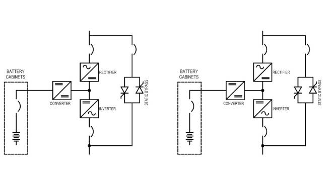
Figure 4: (2) UPS systems running in parallel fed from upstream switchboard. Courtesy: Jacobs
Conclusion
When it comes to designing industrial power systems, many design decisions must be made. This case study shows some of the common key design decisions that must be made in an industrial setting.
Other factors such as site-specific standards, regional codes and standards, equipment lead time and client expectations would impact the overall design decisions to specify a complete and functional electrical distribution system that meets the client’s construction and operational targets.
Do you have experience and expertise with the topics mentioned in this content? You should consider contributing to our CFE Media editorial team and getting the recognition you and your company deserve. Click here to start this process.

Related Resources


